DIYAUDIO forum에서 랭킨이 똑같지 않다고 했슴
느낀점 -- 무지 간단 & 깔끔하다
grid choke -- 8w 이상 뽑는 이유?
It may interrest you, over at DIY Audio the Wavelength Audio Cardinal X1 (the one with the 6S45-P/PE driver) has been reverse engineered.
Photos and schema drawn from the Photo's are in the Photos section of the Audiophile Group:
http://photos.groups.yahoo.com/group/thunderstone_audiophile/lst?.dir=/Wavelength+Audio+Cardinal+X1
Some comments on components used etc I made over at DIYA, based on the Photo's, slightly expanded:
======================================
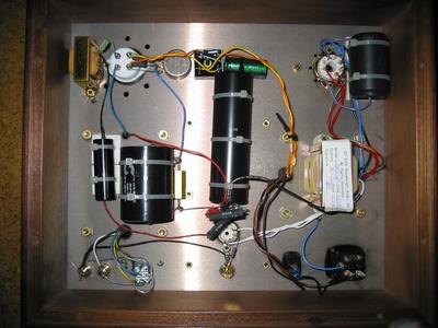
A little decoding around the 300B....
Heaters are DC without much ado, bridge rectifier, and what looks like Nichicon Muse Capacitor 15,000uF, plus the usual Humbuck Pot &Shunted across resistors.
Cathode combo 1K/25W Metalclad Power Resistor with 39uF Solen/SCR MKP Cap as bypass.
The Socket is Yamamoto PTFE and there is a Gridstopper (maybe 1K or less?) and a Magnequest Gridchoke, probably custom Spec., BCP-16/NI or S&B GC should substitute fine.
Coupling Capacitor is unrecognisable, but there are many possible favours. Output Transformer is Magnequest, probably a custom Version of the FS-030. That one has more primary inductance than the Lady Day/Billie one or indeed most Tangop/Tamura/James OPT's for the 300B.
The main Powersupply has a modest value Film capacitor after the rectifier valve (I'd estimate on the size maybe 10 - 22uF), followed by the choke (lower righthand side) maybe around 10H, could be 15-20H and followed by a big Black Gate 2-Section PSU Capacitor (probably 100u+100u/500V WKZ), first section for 300B PSU, the second for the Input Stage.
Amplifier starground is at the BG's negative terminal, but it also seems the Amplifier Plate is used as Groundplane with several components simply returned via this.
The 12K1 Mill Power wirewound visible is the decoupling for the 6S45 PSU and the second 12K1 Mills is the 6S45 Anode load.
There is also the 6S45 cathode combo hidden there, looks like "L Cancelling Pair" Black Gate NX-HiQ & 1/4W (Tantalum?) Cathode R. On the RCA Jack is the Gridleak resistor and the Gridstopper bridges across from the RCA Jack to the Gridpin.
Values cannot be made out but are easy enough to guesstimate, 47K Gridleak, 1K Gridstopper and between 200-300 Ohm Cathode R (I'd adjust for 170 - 200V on the 6S45 Anode).
=========================================================
Hope this gives some ideas.
Ciao T
|