http://home.pacifier.com/~gpimm/Battery_biased_ccs.htm
Updated January 28, 2004
The battery biased CCS just got it's first major update. The board has been redone to use 27A 12 volt alkaline batteries instead of the solder tab lithium coin cells.
There are some tradeoffs. The minuses are the alkaline batteries don't have as flat of a discharge curve and the shelf life is shorter than the lithium batteries . The less stable discharge voltage is offset by making the CCS adjustable. This makes it possible to compensate for the batteries as the voltage drops with age. The pluses are the batteries are much more readily available and easy to change. Radio Shack has them in 2 packs for ~$2.50. It is also very nice to be able to remove the batteries when working on the CCS or moding the amplifier.
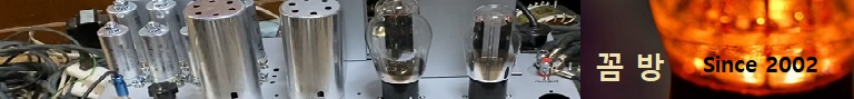
The new battery biased CCS.
The perfomance of the new board layout is measureably better at low frequencies than the old layout. At 100Hz the new circuit measures ~20G ohms where the old layout measures ~6G ohms. Both boards converge at 10Khz and have the same performance above 10K.
Updated September 30, 2002
Protection zener diodes VR1 and VR2 were added. I felt they weren't necessary when the batteries were connected directly to the gate stopper resistors. The batteries themselves protected the mosfets.
Now that B1 is isolated from the gate stopper resistor by 240K, and when used with a pentode on top, B2 is replaced with a 10K resistor, the mosfets need protection.
When building the battery only version R4, R5, CR1, and VR3 don't get placed. When building the pentode version B2 doesn't get placed and R4, R5, CR1, VR3 get placed.
Other changes:
C1 reduced to .01uf. Allows use of the smaller cheaper .01 soviet Teflon's.
B1 isolation resistor circuit designator changed from R4 to R6. (This allowed me to keep R4 for the dropping resistor in series with the CCS diode, like in rev. 3 and rev. 4).
R5 on pentode version changed to 10K.
The board layout was changed to include VR1, VR2, for protection and R4, R5, CR1, and VR3 to support the pentode version. You won't find R5 on the board layout. The pentode version doesn't use B2. Instead, R5 (10K) is placed diagonally across where B2 normally goes, skipping over the 3 short runs that connect the individual cells together.
Here is the battery biased CCS. It is the same mosfet circuit used in Rev 4 with out the pentode and with the bias circuit made as simple as possible. The performance is just slightly behind Rev 4. I suspect the difference is the IRF820 handles the full AC voltage where the upper mosfet in the Rev 4 circuit only deals with about 1% of the AC voltage.
Performance numbers for this circuit is 2G ohms and .3pf shunt capacitance. The listening tests I did on this circuit consisted of installing this circuit in my 26 line stage along with putting the support parts (screen dropping resistor, screen stopper, and the 100uf capacitor) for the 6AU6 pentode on the pentode socket. With this setup I could listen to it with the pentode, power down and remove the pentode, place a jumper plate to cathode in the socket, power the system up and listen to it with only mosfets. After a couple of weeks of switching back and forth I came to the conclusion that I could not tell the difference.
This circuit works good for low to moderate currents at high voltage and high currents at lower voltages. For higher currents at high voltage or high power I still think the pentode on top is the better way to go. It is just easier to dissipate heat in a vacuum tube than a solid-state device with a heat sink. The tubes can radiate a large percentage of the heat where heat sinks rely on convection currents in the air to cool them. Besides, I don't want heat sinks showing on my amps! Been there, done that, don't wana do it again! ;-
Here is a table that should help with selecting R1. These measurements were made on a pair of IRF820 mosfets. IRF510 mosfets have a slightly lower turn-on voltage so the current will be slightly higher than the table shows. The voltage for each cell is assumed to be 3.3 volts.
|